| A Phase Linear Transmission
Line Project |
|
| Section 7: Construction
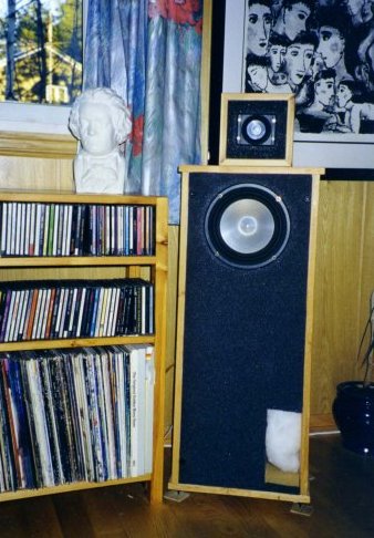
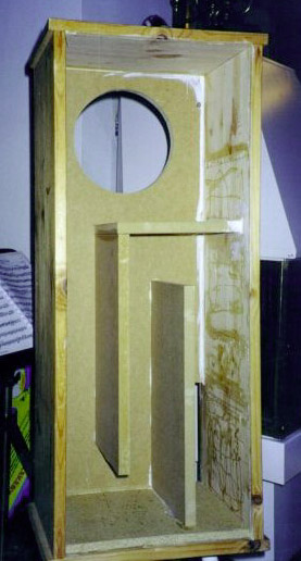
The speaker (Figure 7.1) consists of two cabinets. One TL cabinet (Figure 7.2) for the JX150 woofer and a sealed box placed on top for the JX53 tweeter. Width of the TL cabinet is chosen to fit to the baffle diffraction compensation technique with a 1st order acoustical rolloff at 500 Hz. This is achieved with an electrical 1st order crossover set at 180 Hz. The TL is stuffed with polyester fill (Figure 7.3). I used something called AcoustaQ. AcoustaStuff or any other polyster fill could be used. The cabinet is built as mirrors, so the ports of each speakers come out on opposite sides. This assures port output being symmetrical, not skewing the stereo perspective. An angled panel (not shown in pictures) should be inserted in the loading chamber. This panel is required for the LF response (Figure 7.4). If it is not mounted, the loading chamber acts as an acoustical filter high pass filter, reducing the output below line resonance. The port is placed adjacent to the floor, giving an extra LF boost. Stuffing of the line (Figure 7.3) could be done after the speaker is finished. Having slim arms helps to adjust the fill on the inside. Amounts in the 200-250 g area should work fine for most rooms. |
Figure 7.1. The speaker |
|
Figure 7.2. Transmission line under construction
|
|
| The JX53 tweeter (Figure
7.1) is situated in a small closed box on top of the transmission line. This
reduces diffraction dramtically. Tweeter should be mounted in the slimmest cabinet
possible. (The current cabinet is wider than required.) The tweeter box could be
fastened securely to the TL, or be put on some kind of dampening feet. I am using
sorbothane dampening feet from Sonic Design. Both drivers should be wired in phase, and the distance where they are time aligned at 500 Hz, is with the tweeter recessed 80 mm behind the woofer. This is quite far back compared to other systems, but not strange when considering the low crossover frequency and the compensation for the downward tilt of the 1st order filter summation. |
|
| Sorbothane dampening feet
is my prefered way of coupling the speaker to the floor. This dramatically improves
dynamics and evens out the low frequency response. The details of the crossover are not described here. I prefer to use active filters. The LF filter is 1st order, 180 Hz electrical. HF filter is 1st order 500 Hz. Dividing passively at 180 Hz will require a large inductor. If a passive filter is used, I suggest implementing it at line level, using a series capacitor matched to the input impedance of the power amplifier. Plans Drawings & cutting plan in PDF-format (16k). |
Figure 7.3. The importance of the angled panel. |
|
[ Contents | Intro | Measurements | Optimization | Integration | Step Compensation | Time Align | Crossover | Construction ]
|
|