| Baffle Step Compensation by Alex Megann 30-april-12 |
|||||||||||||||||||||||||||||||||||||||||||||||||||||||||||||||||||||
|
[ OT Articles | Intro | BaffleStep | BaffleStep Compensation | PLLXO | Sallen-Key | XO Design | DiAural ] |
|||||||||||||||||||||||||||||||||||||||||||||||||||||||||||||||||||||
| Baffle Diffraction
Theories and Practice An assumption often stated is that the "baffle diffraction step" is a transition from radiation through 4pi solid angle (equal power at all angles) to a 2pi radiation pattern (power is only radiated to the front of the baffle). This is true for a speaker in an anechoic chamber or outdoors, and in these cases there will be a net 6 dB step (doubling of SPL) at high frequencies relative to the response at frequencies where the wavelength is large relative to the baffle size, with some ripples whose severity will depend on the shape of the baffle and on the driver position on the baffle. In a real living room, though, the speaker will tend to be placed within a metre or two of the rear wall, and in any case low frequencies are not strongly absorbed at boundaries, so most of the rear wave will be reflected by the wall anyway. This means that the compensation theory described in John Murphy's article will give an excessive boost to the low frequencies (or a loss in higher frequencies), since the 6dB compensation doesn't match the loss, which will generally be less that 6dB. When I first put my active crossover together I added a 6dB step compensation circuit, with centre frequency adjustable from 200Hz to 1200Hz. I eventually settled on around 450Hz, since according to John's analysis of Olson's results this corresponds to my baffle width of 25cm. Without the compensation the speakers sounded thin, but with it, even when I played with the centre frequency, they never sounded right - there was always too much energy in the upper bass or too little in the low bass. I changed the resistors in the compensation circuit to get a 3 dB, rather than 6 dB, boost at low frequency, but with the 1.5dB point still at 450Hz. The change was quite striking - there is now more clarity and punch in the bass, and once I had changed the bass level I found the midrange had become more detailed. |
|||||||||||||||||||||||||||||||||||||||||||||||||||||||||||||||||||||
|
|
|||||||||||||||||||||||||||||||||||||||||||||||||||||||||||||||||||||
| The Problem -- to compensate for the power loss at low frequencies as the radiation pattern transitions from 2pi steradians to 4pi steradians. The frequency at which this occurs is a function of the baffle size. | |||||||||||||||||||||||||||||||||||||||||||||||||||||||||||||||||||||
| The Circuit -- the following circuit can be used. It has unity gain at high frequencies and an adjustable gain at low frequencies: | |||||||||||||||||||||||||||||||||||||||||||||||||||||||||||||||||||||
|
|
|||||||||||||||||||||||||||||||||||||||||||||||||||||||||||||||||||||
| The response is | |||||||||||||||||||||||||||||||||||||||||||||||||||||||||||||||||||||
|
|
|||||||||||||||||||||||||||||||||||||||||||||||||||||||||||||||||||||
| and the magnitude of the response is | |||||||||||||||||||||||||||||||||||||||||||||||||||||||||||||||||||||
|
|
|||||||||||||||||||||||||||||||||||||||||||||||||||||||||||||||||||||
| If we define the magnitude of the
low-frequency limit as |
|||||||||||||||||||||||||||||||||||||||||||||||||||||||||||||||||||||
|
|
|||||||||||||||||||||||||||||||||||||||||||||||||||||||||||||||||||||
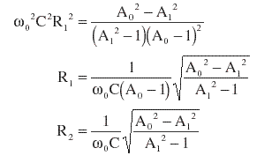
| At some frequency w0 let the desired response be A1, which we choose to be some sensible value between unity and the DC limit A0. I chose the geometric mean, equal to the square root of A0, which gives the midpoint of the step on a decibel scale. Then we can calculate the values of both the resistors: | |||||||||||||||||||||||||||||||||||||||||||||||||||||||||||||||||||||
|
|
|||||||||||||||||||||||||||||||||||||||||||||||||||||||||||||||||||||
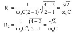
| 6dB Step | |||||||||||||||||||||||||||||||||||||||||||||||||||||||||||||||||||||
|
|
|||||||||||||||||||||||||||||||||||||||||||||||||||||||||||||||||||||
| This is required to compensate
for the diffraction loss of a speaker in free space. If |
|||||||||||||||||||||||||||||||||||||||||||||||||||||||||||||||||||||
|
|
|||||||||||||||||||||||||||||||||||||||||||||||||||||||||||||||||||||
| If C = 116 nF and w0
= 2pi x 450 Hz (for a 25 cm baffle), R1 = R2 = 4311 W. John Murphy suggests the following model response for the effect of diffraction for a baffle of width Wb: |
|||||||||||||||||||||||||||||||||||||||||||||||||||||||||||||||||||||
|
|
|||||||||||||||||||||||||||||||||||||||||||||||||||||||||||||||||||||
| where |
|||||||||||||||||||||||||||||||||||||||||||||||||||||||||||||||||||||
| 3dB Step | |||||||||||||||||||||||||||||||||||||||||||||||||||||||||||||||||||||
|
|
|||||||||||||||||||||||||||||||||||||||||||||||||||||||||||||||||||||
| In a real-life listening room,
some of the diffracted sound will be reflected back towards the listener. In this
case the loss will be less than 6 dB*. If we choose |
|||||||||||||||||||||||||||||||||||||||||||||||||||||||||||||||||||||
|
|
|||||||||||||||||||||||||||||||||||||||||||||||||||||||||||||||||||||
| and | |||||||||||||||||||||||||||||||||||||||||||||||||||||||||||||||||||||
|
|
|||||||||||||||||||||||||||||||||||||||||||||||||||||||||||||||||||||
| Using C = 116 nF and w0=2pi x 450 Hz, R1 = 8753 W and R2 = 3626 W. | |||||||||||||||||||||||||||||||||||||||||||||||||||||||||||||||||||||
| * John Murphy has some really good comments on this subject. | |||||||||||||||||||||||||||||||||||||||||||||||||||||||||||||||||||||
|
I calculated component values for a switchable equaliser, with a choice of step frequencies and either five (1.5dB steps) or seven (1dB steps) low-frequency gains. These are based on a value for C of 100nF for a step centred at 1kHz, and are as follows:
|
|||||||||||||||||||||||||||||||||||||||||||||||||||||||||||||||||||||
|
[ Back to T-Line Speaker Page | OT Articles ] [ Intro | BaffleStep | BaffleStep Compensation | PLLXO | Sallen-Key | XO Design | DiAural ]
|
|||||||||||||||||||||||||||||||||||||||||||||||||||||||||||||||||||||


