Not just another Daline
by Chris Bobiak |
|
Speakers
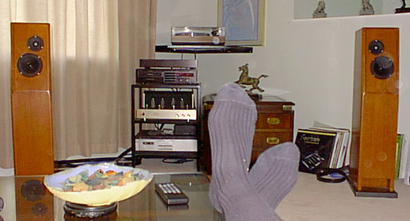
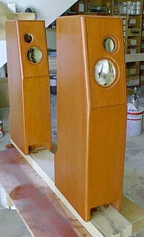
in room. Enjoying the results.
<clik on most images
for a larger picture>
[ Daline
| System | Plans ]
 |
If ever a web page needed
a personal dedication, this one goes to my long suffering, much better half, Susan
Donell B, for her never ending patience, and to Dr. D., for guidance, humor, and
spare parts.
Math aficionados, proceed at your own risk, while there may be some soft core arithmetic
later,
-- This is a MATH FREE ZONE.
Still here? OK let's go.
Like many of the readers of this site, I've been playing around with audio gear for
quite a few years. Long enough actually that the first console my parents let me
muck about with was mono, with one of those 60's Garrard changers with the art deco
5 pound tone arm, and some kind of tubed electronics.
Since getting a little more serious in the early 70's, I've seen a lot of gear
(and dollars!) come and go, some that I'd never admit to now, others that could still
get the mid-fi nod today.
I've always liked to tinker with my toys, so there was some tweaking etc., assembly
and mods to Hafler amps, the usual stuff. More recently blasting off the occasional
enclosure for car audio subs. But aside from a couple of pair of RSC factory kits
(remember Radio Speakers of Canada? -- whatever happened to them anyway?), building
a home audio speaker was always a bit intimidating. The KEF kits of the 70's just
never did it for me musically, but I think it was the math required for customized
crossovers that scared me the most.
Well technology sometimes progresses in a positive direction, and surfin' the net
reintroduced me to the idea of rolling my own. The range and quality of drivers and
information available to the newbie constructor is almost mind boggling, and if you
spend enough time researching, you don 't even have to do any complicated math. (Do
I hear an AMEN?) |
| |
|
|
With all due respect to
the quality of research, engineering, build quality, and sonic performance of the
manufacturers of the better audio gear, it's just so easy today for a DIY'er to create
a very musically satisfying loudspeaker for a relatively modest cash outlay. This
is particularly true if you can leave your old prejudices and conventional wisdom
at the door, and start with a blank sheet. Of course the economics of (inter)national
marketing a wide range of products, and the profit goal of any healthy business contributes
to the ultimate cost. But eventually most of these products are rather cookie cutter
as far as style is concerned. I think most readers that would follow a page this
far would agree that a loudspeaker is the easiest component for most of us to build,
and one that allows a high degree of personal aesthetic expression, both sonically
and visually.
There were several inspirations for this project that should be mentioned. I readily
admit to liberating ideas from these sources, as well as adding a few of my own.
Lynn Olson's Ariel
-- I think this started it all for me.
Arguably not a true T-line, but I was captivated by the very well documented journey
undertaken during the development of this design. I had considered it for my first
project. The cabinet design, though certainly not an afternoon project, was not the
most intimidating factor. Neither was the crossover -- it had already been worked
out. There were numerous builders' sites full of enthusiasm, and with tons of useful
and insightful information.
Ultimately, though it's the cost for a first time project that deterred me.
Scanspeak tweeters, that "non-minimalist" crossover, and intricate enclosure
-- easily over $1,000 CDN. But it is still interesting, and maybe in a couple of
years... |
|
 |
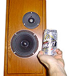
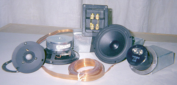
The main legacy of this
source was the selection of the Vifa mid-bass driver (P13WH-00). This has got to
be one of the best values for the DIY 'er. OK, it won't rock the house like a 12"
Shiva in a 3 ft3 ported enclosure -- which I found I can't use anyway.
(Never underestimate the power of the room.) You can start with a very basic low
pass filter for this driver if using sub(s) or none at all. The midrange is really
good. (Search elsewhere for rhapsodic elucidations -- it just sounds wonderful, natural,
and effortless when used within its range and power limits)
There have been numerous improvements to the enclosure, the design becoming more
sophiticated along the way -- the most recent including sand filled chambers
etc.Since the beginning, the Ariel has used 2 of these drivers, each in a separate
"labyrinth / line", sand filled chambers etc. Call it a T-Line if you like.
As this speaker was designed for low powered tube amps (SET particularly), the increased
output using 2 drivers is significant. To simplify my first project, and as power
was not as much a concern for me, I decided on one per side. |
|
The two other sites that
influenced the enclosure design were ORCA's Daline -- 3D visualization, and Meadowlark.
Another interesting site - Steve Deckert's High Performance Audio. Not really a speaker building
site, but just a fun ride. |
|

Drivers & Bits
|
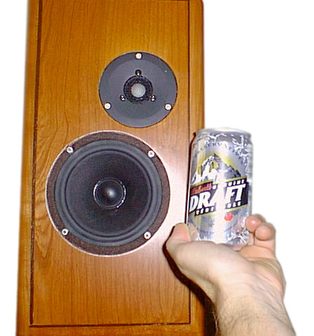
As for the tweeter, I
'd just so happened to have lying around a pair of pretty nice sounding 3/4"
domes from a factory upgrade to my current commercial loudspeaker. This is an OEM
unit, about which little is known other than it is a ceramic or composite dome, the
impedance is rated at 6 ohms, and the crossover frequency in the manual states 2.8kHz.
Depending on your point of view they either didn't cost me anything, or are worth
about $125 each. |
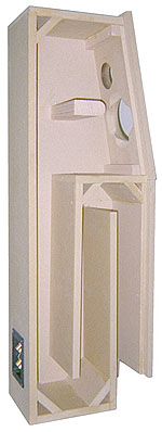
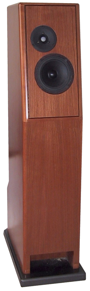
Some minor modifications
to the initial Daline enclosure design resulted in a two-fold line with a length
of approx. 1730mm (68"), and a 10 degree slant to the upper portion of the box.
I figured this would help with time alignment of the tweeter, as well as vertical
dispersion, and I just like the way it looks. The finished front baffle is 1.25"
thick. As is common with many of the better drivers of this size, it is essential
to chamfer the backside of the opening, due to the diameter of the magnet assembly
and shallow mounting depth.
[ Plans ] |

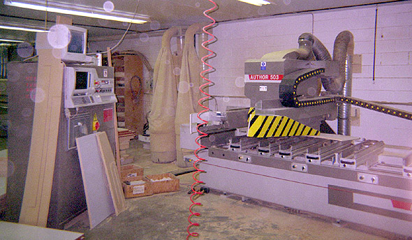
The computerized milling
machine Chris used to build the side panels
|
Layout and machining the
dadoes for the internal baffle would be rather tricky by hand. It is pretty darn
handy to have access to a CNC router. Using basic CADD software (Autosketch/ MiniCad
etc) draw the side gables, including all route patterns. Convert to DXF format, import
to the CAM and away you go. Well, not quite as simple as downloading the latest Norton
virus definitions but it works.
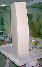
Every new design has its teething process, and as an official T-line virgin, I can
say that getting the stuffing just right is the biggest pain. The mathematically
talented can calculate models, or refer to charts or graphs, but eventually you will
need to listen and adjust it in a real room. As I knew there would be some mucking
about here, I built the box as a rough case with one side removable, to be finished
later.
The shell, internal baffles and bracing are 19mm MDF. Selected use of Baltic birch
or Apple ply would probably improve some aspects of the sound, however the price
factor is significant*.
I used shorter, #6 screws the first few times the box was taken apart, finishing
off with 2" #8 Lo-roots. Okay, cringe if you like, but as I knew the joints
would have to come apart numerous times, I made the planed the baffles on the "free"
side approx. (1 mm) under the dado size. Forcing the parts to a very tight fit several
times to adjust the damping risks some damage to the material. Alright,
I'll be honest, this happened with the first set of gables -- all of the inside diagonal
corner braces broke on one of the boxes.
The premium grade MDF and the dadoes were each exactly 3/4". That makes for
a wonderfully deadly tight joint, which would hold more that adequately with decent
glue, no screws required. Just don't try and take it apart more that once. There
is a lot of surface area involved in these internal dadoes. (Approx 1500mm lineal
x 5mm deep = 7500 mm2) That's a lot of friction. |
| |
*Note: on
Materials
|
|
| |
|
|
| |
19mm (3/4") MDF =
about $20 per 4'x8' (32 ft2) vs Baltic birch @ $45 for 5'x5' (25 ft2).
My math calculates this as $.625 vs $1.80 per ft2. Apple ply is generally
an architectural grade of material, with at least one face of select grade finish
veneer (ie Maple). It can be very gorgeous when finished well, and easily cost over
$100 per sheet.
Note that true 13ply Baltic birch comes in 5'x5' ft sheets, which can give poor cut
yield. Enclosure costs rise dramatically when 1 more sheet is required for a single
gable. Working in a commercial millwork shop has numerous advantages, access to all
the right power toys, and ample "offcuts" (read "free") of MDF
and finishing plywood to be recycled. Just scale the cabinet carefully, prepare a
detailed cut-list, and wait by the scrap bins. (Lumber prices can fluctuate, all
prices quoted are circa May 2000, and CDN$. As always, YMMV)
Note; when purchasing your material, -- there is a significant variation in quality
of MDF. Some of the "utility or shop" grade board doesn't hold a screw
on edge worth a damn -- whether you predrill and use Lo-Root screws or not, the board
will split. There goes the holding power of your fasteners. Whether you intend to
simply fill screw holes and paint the finished product or skin with plastic laminate
or veneers, use only premium grade MDF (ie paint grade Ranger brand or similar) This
material may not necessarily be available at your local Home Depot, etc, try wholesale
commercial distributors. They are also more likely to stock different sizes. (MDF
is widely available through these sources in sheet sizes up to 5x10' and up to 1
1/4" thick. That's 5.2 bd. ft = 230lbs! ) |
|
| |
|
|
|
|
 |
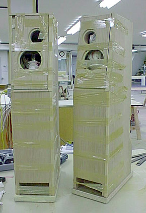
Chris
reveals the secret method used to hold the finish wood in place.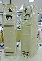
|

|
|
|
| MDF will machine to an
extremely accurate edge with the right tooling, and while the finished surfaces are
casehardened, the machined edges are fragile. Just drop a piece and see what happens
to your edge. It can fracture or mushroom, rendering the joint useless. Upon completion
of the damping exercise, I used enough yellow carpenter's glue to ensure filling
joints. This is where the prototype suffers. Having determined the adequate amount
of damping, subsequent enclosures could be built with superior joinery, as they would
be assembled just once. |
|
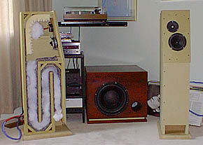
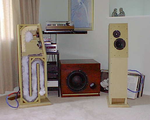
Speakers in room. The
sub is a ported Shiva which completely over-powered the room and has since found
another home.
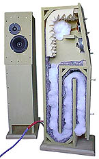
Note: stuffing in an
early stage -- finished speaker has less
|
Using a very basic (3.3
mf ploy cap) crossover for initial listening sessions in 2 different rooms/systems
the damping was finalized.
I definitely overstuffed at the beginning, with very low bass output, and excessive
midrange from too low an overlap between the tweeter and the Vifa. Remember this
driver goes smoooooth well past 3K, no peak, then just rolls off nicely - how cool
is that for a first time project? This subjective observation was confirmed by technical
measurement by Dr. D and his amazing Technicolor PowerBook
The end result was to line the outside shell (gables, front and back panels) with
" Deadliner", line both side of the upper cavity and one side of the line,
including the folds, with 1" Rockwool. |
|
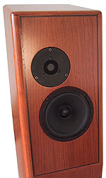
Next step was to "finish"
the box, using a skin of 1/4" cherry plywood, and several layers of contact
cement to attempt somewhat of an constrained layer affect. Solid cherry trims, radiused
to 1" on the front baffle, and wenge inlay on the upper baffle. Some stain and
4 or 5 coats of hand cut lacquer. The bases are slabs of 11/4" MDF, with T-nuts
& speaker spikes, and finished with Tremclad Hammerite enamel. BTW the stain
obscured the wenge inlays too much - oh well.
Further listening confirmed the crossover needed further work. Using readily available
(not the best quality) parts to finalize the voicing of the system, we settled on
0.5 mH coil to slope down the high end on the mid bass, and 1.8mF cap in series with
the tweeter (with a separate impedance compensating C/R leg). The circuit is mounted
on the outboard pod at the rear of the speaker, with rubber bevel washers to further
isolate the point to point wired circuit board.
This configuration sounded quite fine, thank you very much, and the Solen Hepa-Litz
coil and Fast caps further enhanced performance.
The system is bi-wired, using Nordost flatline (copper) cable internally. Sounds
great, but a little tricky to get used to working with. When budget permits, the
system will be bi-amped, whether passively or actively isn't certain at this point.
The existing network is just about as simple as you can get, and seems to work fine,
so let's not fix it?
|
A
Toast to the Music
|
|
|
|
[ <-- Back to TL
Page | Projects | Daline | System | Plans ]
|


