Lanzar 2050, 2100, 4100 Schematic
recovery project
|
| The provided schematics
are poor photocopies of much larger documents and only give you the general idea.
To properly utilize these devices will require more information than they can give
us. |
This is a 1st pass at
redrawing the scematic for the Lanzars. It looks like the 2050 & 2100 share the
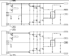
same 'preamp' stage. The 'output' stage on the 2100 has 4 more transistors and (at
least a few) different component values. I haven't got a 4100 scematic.
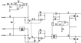
The 'preamp' part of the board -- lo pass, volume & bass-boost sections. I have
labeled some of the components. Some of those may even be right.
Can also be made available in many other formats by request (pdf, eps, dwg, dxf,
minicad...) |

Preamp Stage: Clicking on the thumnail
of the schematic will get you are much larger gif (19k -- should print at 150 dpi
on a legal page).
|
|

2100 Output Stage: Clicking on the thumnail of the schematic will get you are much
larger gif (17k -- should print at 150 dpi on half a letter page).
|

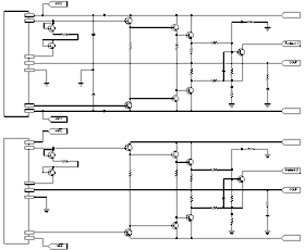
2050 Output Stage: Clicking on the thumnail of the schematic will get you are much
larger gif (15k -- should print at 150 dpi on half a letter page).
|
| 2100 Power Supply:
Patience Grasshopper |
2050 Power Supply:
Patience Grasshopper |
|
How you can help
I need interested BASSList
to download the schematic and help flesh out this document:
- All components need
to be correctly labeled. People who can convert the resistor colors into numbers
in their heads and people who can see close-up well enuff to read off the cap values/semiconductor
labels (and make sense of them in the case of the semiconductors) or would all be
useful here. Some of the components obsure their label, these will need to be puzzled
out.
- Check for topology
differences between supplied schematic & a real amp if any
- Descriptions of the
Lo Pass and Bass-Boost circuitry. Suggestions on how these many be modified (or bypassed).
Things such as changing the cross-over point or slope. Changing the lo-pass into
a hi-pass.Changing the lo-pass into a subsonic. Can the Bass-Boost act as a Bass-Cut.
Can this circuit be rejigged to do something else? Will require those that actually
know how these things work.
- Other tweaks. For
example: better ICs, seperate levels on each channel, better components in critical
areas
- Details of an AC (home)
power supply.
- Node voltages from
a working amp in order to repair the defective ones, voltages at idle
I'll do the actual
drawing. You can mail me text descriptions, annotated gifs, or FAX me ones you have
scribbled on (email for FAX#)
|
|
[ The Transmission Line Speaker Page | Home | Schematic | Pictures | Examples | Bridging]
|


